TM 5-4240-5501-148P
STARTERS
Gear Drive 12V & 120V
CAUTION: The test of this rectifier assembly requires the
use of a 120 volt AC circuit. Extreme care should be
used when making this test to minimize the hazard of
electrical shock.
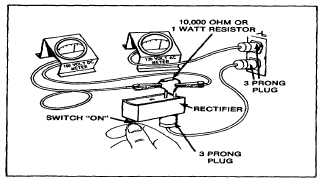
Solder the 10,000 ohm resistor to the DC internal
terminals of the rectifier, as shown in the accompanying
illustration. Fig. 119.
Fig. 119 - Checking Rectifier Assembly
Connect the DC volt meter between the rectifier field
terminal and the brush terminal. Fig. 119.
Measure the line voltage of the 120 volt AC outlet to be
used. A rectifier assembly in good condition will be
within the following specifications: 1. With the switch in
the off position, a zero reading should be observed on
the DC volt meter.
2. With the switch in the on position, the DC volt meter
reading should be 0 to 14 volts lower than the AC line
voltage measured previously.
If the drop exceeds 14 volts, the complete rectifier
assembly must be replaced, as individual parts for the
rectifier assembly are not available.
ASSEMBLY OF STARTER MOTORS
When all parts have been thoroughly inspected, lightly
lubricate the bearings with #20 oil and reassemble in the
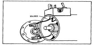
following manner. (Solder the field lead to the rectifier
assembly and assemble the rectifier to the housing (120
VAC motor). Fig. 120.
Fig. 120 - Installing Rectifier to Housing
Insert the brushes in their respective holders.
NOTE: A tool such as shown in Fig. 45 should be used
to hold the brushes clear of the armature commutator
when assembling the commutator end cap to the motor
housing.
Fig. 121 - Inserting Brushes
Fig. 122 - Installing End Cap
Slide the armature into the motor housing, being sure to
match the drive end cap keyway to the stamped key in
motor housing. Assemble end cap, again matching the
keyway to key in housing. Care should be used to
prevent damage to ceramic magnets where used.
Assemble thru bolts, lockwashers and nuts.
NOTE: THRU BOLTS AND NUTS MUST BE PLACED
IN THE SAME POSITION AS WHEN REMOVED OR
INTERFERENCE MAY RESULT.
After Hi-Pot test and assembly of the starter motor drive,
the starter motor is now ready for installation to the
engine.
35


