TM 5-4240-5501-148P
STARTERS
Gear Drive 12V & 120V
DISASSEMBLY OF STARTER MOTORS
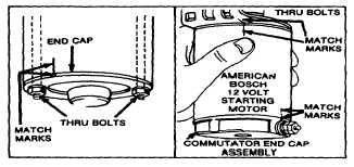
Remove the lockwasher, nuts and thru bolts. See Fig.
116. The armature, drive cap and gear drive can now be
removed as an assembly.
NOTE: THRU BOLTS AND NUTS MUST BE PLACED
IN THE SAME POSITION AS WHEN REMOVED OR
INTERFERENCE MAY RESULT.
(See checking starter motor drive if repair, cleaning or
replacement of drive assembly is necessary.)
Fig. 116 Removing Thru Bolts
CAUTION: Do not clamp the motor in a vise or strike the
motor with a hammer. Some motors include two
powerful ceramic magnets which can be broken or
cracked if the motor housing is deformed or dented.
To remove the commutator end cap, lift the brush
springs and slide brushes out of the brush holders. The
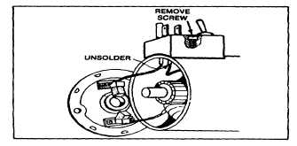
120 volt AC starter motor rectifier assembly may now be
removed by loosening the cover screw and unsoldering
the field lead attached to the rectifier assembly. See Fig.
117.
Fig. 117 Removing Rectifier
Clean all dirt or corrosion accumulations from the
armature, commutator end cap, drive end cap, etc. The
bearings, housing and armature should not be soaked in
a cleaning solution. The armature commutator may be
cleaned with a fine sand paper. Do not use emery cloth,
as emery will embed in the commutator and cause rapid
brush wear. If it is suspected that the armature, field coil
or motor housing is defective, new parts should be tried
in the motor. If proper testing equipment is available,
check the suspected armature or field coil to determine if
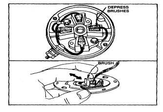
it is defective. The brushes should be checked for
proper seating, weak brush spring, dirt, oil or corrosion.
Brush spring pressure should measure from 4 to 6
ounces when pressed to working position. Also check to
be sure brushes are not sticking in their respective brush
holders. See Fig. 118.
Fig. 118 Checking brushes
CHECKING THE RECTIFIER ASSEMBLY 120 VOLT
AC STARTER MOTOR
The rectifier assembly consists of a spring loaded switch,
which is in a normally "off" position, an AC three wire
ground receptacle and four rectifiers encapsuled in an
epoxy case. The test procedure for checking the rectifier
is as follows:
Equipment Needed
1.
An AC volt meter capable of measuring 120 volts
AC.
2.
A DC volt meter capable of reading 100 volts
DC.
3.
A 10,000 ohm resistor (1 watt).
34


