TM 5-4240-501-14&P
STARTERS- Briggs & Stratton
Gear Drive 12V & 120V
Mark the center of the rivets holding the ring gear to
flywheel, with a center punch. Drill out the rivets using a
3/16" (4.8 mm) drill. Clean holes after drilling. Fig. 83.
Attach new gear to flywheel using four screws and lock
nuts provided with gear.
CHECKING STARTER MOTORS
If a starting problem is encountered, check the engine
thoroughly to be sure it is not the cause of starting
difficulty. It is a good practice to remove the spark plug
and rotate the crankshaft by hand, to be sure it rotates
freely. Any belt, clutch or other parasitic load will affect
cranking performance.
Service procedures for both the 12 volt and 120 volt
starter motors are similar and will be covered together,
except where noted otherwise.
A list is provided to aid in diagnosing problems for 120
volt DC and 120 volt AC systems. See page 9 and 10.
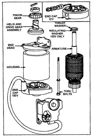
Fig. 84 - 12 Volt & 120 Volt Starter Motor -
Exploded View
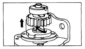
CHECKING STARTER MOTOR DRIVE
When the starter motor is activated, the pinion gear
should rise, engaging the flywheel ring gear and crank
the engine. This action can be observed by removing
the starter shield. If the starter motor drive does not
react properly, inspect the helix and pinion gear for
freeness of operation. If any sticking occurs, this must
be corrected. Proper operation of the starter is
dependent on the pinion freely moving on the helix. See
Fig. 85.
Fig. 85 - Checking Starter Motor Drive
DISASSEMBLING STARTER MOTOR DRIVE
To
remove
the
drive
assembly
for
cleaning
or
replacement, disconnect and remove starter from
engine. Place in "V" block as shown in Fig. 87. Drive
the roll pin out with a hammer and 1/8" (3.2 mm)
diameter punch to remove the retainer.
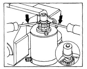
NOTE: Some starter drive assemblies utilize a gear
return spring. These are protected with a plastic cap
over the drive assembly. Carefully snap the plastic cap
from the cup using two screwdrivers. See Fig. 86.
Fig. 86 - Removing Cap Assembly (Some Models)
24