TM 5-4240-501-14&P
STARTERS
Gear Drive 12V & 120V
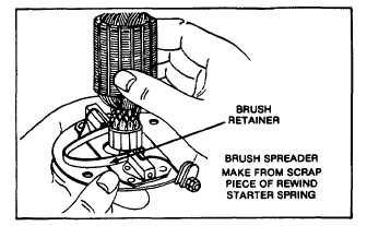
Fig. 78 - Assembling Armature to End cap
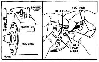
If 120 volt motor, connect rectifier to end cap as shown in
Fig. 79 with 1/4" nut driver.
INSTALL LEADS IN EXACT POSITION SHOWN.
Fig. 79 - Installing Rectifier Assembly
Support armature shaft and slide it slowly into housing,
as shown in Fig. 80. Insert rubber mounted terminal into
housing at this time.
Fig. 80 - Inserting Armature
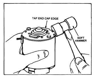
Place thrust washer on motor PTO shaft. Install end
head and thru bolts. Align end cap and end head match
marks correctly. Fig. 74. Tighten screws. Tap edge of
end cap using a soft hammer to align motor bearings if
required. Fig. 81. Check armature shaft for end play.
Armature should rotate freely.
NOTE: 120 VOLT MOTORS HAVE TWO POSSIBLE
HOUSING
POSITIONS.
INTERFERENCE
MAY
RESULT IF CORRECT POSITION IS NOT USED. FIG.
74.
Fig. 81 - Aligning Bearings
Test performance of starter motor. Page 19 or 20. If
starter motor tests as specified, continue assembly.
HI-POTENTIAL TEST (HI-POT)
WARNING: A Hi-Potential Test of the 120 Volt AC starter
motor must be conducted prior to installation of starter
motor to engine.
DANGER: High voltage is used in this test. Exercise
extreme care to minimize the hazard of electrical shock.
If test equipment is not available, take starter motor to a
local electrical motor repair shop for test. Failure to
perform this test may present an electrical hazard. If
starter motor tests are positive, continue assembly.
22