ALTERNATOR
Tri-Circuit
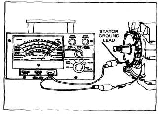
TESTING STATOR COILS
With multimeter, check continuity between ground lead
to stator coil and output connector lead shown in Figure
209. Meter should show continuity. If meter does not
indicate continuity, replace stator.
Fig. 209 - Checking Continuity
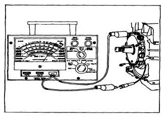
Next, be sure ground lead terminal is not touching a
grounded surface. Check continuity from terminal to
ground. See Fig. 210.
Meter should not show continuity. If meter indicates
continuity, coils are grounded and defective. Examine
lead to be sure the insulation is not -worn or cut. Repair
with tape and shellac if a bad spot is found. If ground still
exists, sator must be replaced.
Fig. 210 - Checking for Grounded Wire in
Stator Assembly
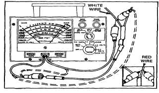
CHECKING DIODES
Disconnect charge lead from stator output lead. Using a
multimeter set on resistance scale, check diodes by
attaching one meter lead to connector pin. Touch the
other meter lead to the white wire (light circuit diode),
then reverse meter leads. Meter should show continuity
in one direction only. Repeat this procedure for the red
wire (battery charging diode). Meter should show
continuity in one direction only. If meter shows continuity
in both directions or does not show continuity in either
direction, the diode harness must be replaced. See Fig.
211.
Fig. 211 - Checking Diodes in Wire Harness
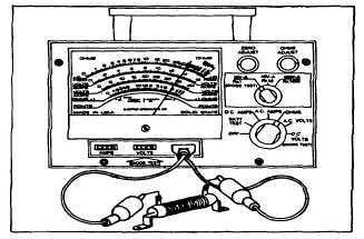
The resistor that reduces battery charging current should
also be checked when testing alternator. See Fig. 212.
An acceptable resistor should have approximately one
ohm resistance. Also check to be certain the double
pole switch is operating properly. See Fig. 207.
Fig. 212 - Checking Resistor and Switch
65