ALTERNATOR
10 Amp
10 AMP REGULATED ALTERNATOR
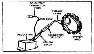
The 10 amp regulated alternator incorporates a system
in which the charging rate is regulated to the battery.
The stator is located under the flywheel and is similar to
the Dual Circuit stator and Tri-Circuit stator.
Fig. 213 - 10 Amp Alternator Assembly
There are two leads from the stator, similar to the dual
circuit alternator, but of the same color. Fig. 213. The
charge rate to the battery is 10 amps and less than 0.2
horsepower is used to operate the system. In the
regulator box assembly there are diode rectifiers and
S.C.R. (Silicon Controlled Rectifiers) which convert
alternating current to direct current for charging the
battery, and regulating the voltage.
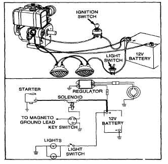
Fig. 214 - Typical Wiring Installation
CHECKING ALTERNATOR OUTPUT
NOTE: There will be no charging output unless a 12 volt
battery with a minimum of 5 volts charge is connected to
the output side of the regulator. See Fig. 214.
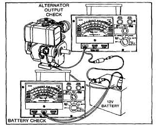
To check the 10 amp system, first make sure the battery
is at a minimum of 5 volts. With a VOA meter, check the
amperage output of the regulator. Attach the meter in
series (see Fig. 215) on the positive side of the charging
circuit. Start the engine and run at normal operating
RPM. If battery voltage is at its maximum the charging
current will be less. An example would be if the battery
voltage reads 14 volts, the amperage would probably
read less than 3 amps. If the battery voltage reads 10
volts, the charge current will read approximately 10
amps.
Fig. 215 - Checking Output of 10 Amp Regulator
TESTING STATOR COILS
With a multimeter, check continuity of the stator
windings; this can be done by disconnecting the plug
connector. See Fig. 216. Use a VOA meter set on the
low ohm resistance scale. Touch one terminal with a
probe and the other terminal with the remaining probe.
Continuity should be present. If no continuity is present,
this would indicate an open in the stator windings.
Remove flywheel and repair or replace stator. To check
for a grounded stator winding, repeat the above
procedure, but attach one probe to ground, Fig. 217. If
continuity is present, this would indicate a grounded or
“shorted” stator winding.
66


