SYNCHRO-BALANCE
Oscillating Counterbalance
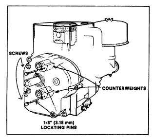
To do so remove two small screws from cover and insert
1/8" (3.18 mm) diameter locating pins through screw
hole and into timing hole provided in counterweights, Fig.
6.
Fig. 6 - Timing Counterbalance Gears
With the piston at TOP DEAD CENTER, install the
crankcase cover assembly and cover gasket. Remove
the locating pins. Coat threads of timing hole screws
with a non-hardening sealant, then install screws and
fibre sealing washers.
If counterweights are removed from crankcase cover,
exercise care in handling or cleaning to prevent losing
needle bearings.
ASSEMBLY OF COUNTERWEIGHTS
Install counterweights on shafts in crankcase cover.
Install counterweight retainers and torque screws to 50
inch pounds (.57 mkp or 5.6 Nm).
SERVICE PROCEDURES FOR
MODEL SERIES 171700, 191700,
251700 & 252700 OSCILLATING
COUNTERBALANCE SYSTEM
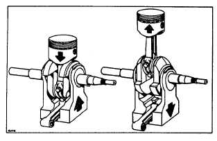
Fig. 7 - Oscillating Counterbalance
Disassembling Oscillating
Counterbalance
Use a screwdriver and hammer to open the connecting
rod cap screw locks - remove connecting rod screws -
remove connecting rod and piston assembly. Remove
crankshaft and counterweight assembly. Remove
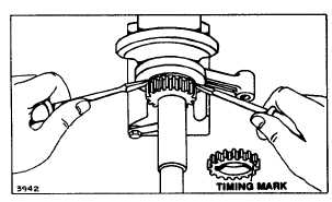
crankshaft gear - in the event it should fit tight, it can be
pried off with two screwdrivers, being careful not to
damage the gear. Fig. 8. Save the key on MODEL
SERIES 171700 only. Key is staked in on MODEL
SERIES 191700, 251700 and 252700.
Fig. 8 - Removing Crankshaft Gear
Disassemble the counterweight. Open the locks and
remove one or two screws holding the halves of the
counterweight together. Separate and remove the dowel
pin. link and spacer. Fig. 9.
3