SYNCHRO-BALANCE
Rotating Counterbalance
Section 12
SYNCHRO-BALANCE
Briggs & Stratton uses two methods of Synchro-
Balancing engines.
One system uses counterweights that are geared to
rotate in a direction opposite from the crankshaft
counterweights. The other system uses a counterweight
that oscillates opposite to the direction of the piston.
Each system performs the same function of substantially
reducing engine vibration, thereby giving exceptionally
smooth engine performance.
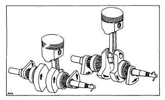
Fig. 1 - Cast Iron Engines,
Rotating Counterbalance
ASSEMBLING AND TIMING
ROTATING SYNCHRO-BALANCERS,
CAST IRON ENGINES
Remove all traces of oil or dirt from tapered surfaces of
drive gears and cam shaft before assembling gears to
camshaft. Turn crankshaft until piston is at top dead
center.
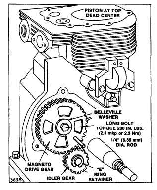
Remove long 5-1/2" (139.7 mm) cam gear shaft bolt,
place magneto drive gear on cam gear taper. Install bolt
with Belleville washer, finger tight. See Fig. 2.
Fig. 2--Installing and Timing
Magneto Drive Gear
On MODEL SERIES 300400 and 320400 only, place
PTO drive gear on the other end of camshaft. Install
short cam gear bolt with Belleville washer, finger tight.
See Fig. 3.
To time drive gears, insert short pieces of 1/4" (6.35 mm)
rod through 1/4" (6.35 mm) holes in drive gears, and into
locating holes in crankshaft bearing support plates. Fig.
2. For MODEL SERIES 300400 and 320400 also see
Fig. 3. With piston at exactly TOP DEAD CENTER,
torque cam gear bolt(s) [with 1/4" (6.35 mm) rods in
place] to 200 inch pounds (2.3 mkp or 22.6 Nm) . Be
certain piston does not move. Remove the 1/4" (6.35
mm) rods.
Install idler gear (s). Install snap-in "E" rings to retain
gears. No timing is necessary. Figs. 2 and 3.
JUNE 1981
1