SYNCHRO-BALANCE
Rotating & Oscillating Counterbalance
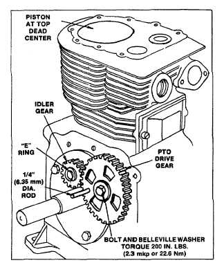
Fig. 3 -- Installing and Timing PTO Drive Gear
The counterweights and ball bearings are an integral part
of the covers, and cannot be removed. Lubricate the ball
bearings and gears with a few drops of engine oil.
PISTON MUST BE AT TOP DEAD CENTER.
Remove the timing hole screw from cover assembly.
Fig. 4. Insert a short piece of 1/8" (3.18 mm) rod
through timing hole in cover and into maching hole in
counterweight. Fig. 4. The rod holds the counterweight
in the proper position while cover is installed on engine.
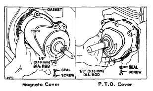
Fig. 4 - Removing Timing Hole Screw
Install cover assembly and gasket. using care to avoid
damage to oil seal and making sure that bolt holes line
up with tapped holes in cylinder. To minimize gear
backlash. push magneto side cover toward idler gear
and torque bolts to 120 inch pounds (1.4 mkp or 13.5
Nm). For MODEL SERIES 300400 and 320400 repeat
above for PTO cover, torquing bolts to 200 inch pounds
(2.3 mkp or 22.6 Nm).
Remove timing rods. Coat threads of timing hole screw
with a non-hardening sealant, then install screw and fibre
sealing washer.
MODEL SERIES 251400, 252400 &
253400
These
Model
Series
utilize
two
gear
driven
counterweights in constant mesh with the crankshaft
gear.
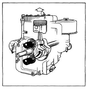
The cut-away view illustrates these gears, mounted in
the crankcase cover, and how the Synchro-Balance
counterweights rotate in opposite direction to crankshaft
rotation, Fig. 5.
Fig. 5 - Aluminum Engines Rotating Counterbalance
System
SERVICE
PROCEDURES
FOR
MODEL
SERIES
251400, 252400 & 253400
The gear driven counterweights must be properly aligned
when cover is installed.
2