SECTION IV: SEAT ASSEMBLIES
TM 9-2350-256-20
3
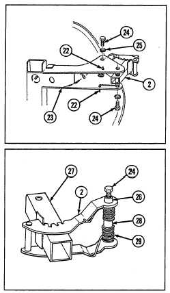
Snap ends of two springs (22) out of holes in
support assembly (23).
NOTE
Remove upper screw (24)' first. Insert a
drive pin punch in upper screw hole
while removing lower screw (24) to
prevent binding.
4
Remove retainer assembly (2) from support
assembly (23) by removing four screws (24), four
lockwashers (25), and two springs (22).
NOTE
Hollow threaded rod (26) can be pulled
out of retainer assembly (2) in same
manner as pulled out of adjuster
assembly (27) in step 5.
5
Use one screw (24) (removed in step 4) and pull
hollow threaded rod (26) out of spacer (28).
Remove spacer and two springs (29) from
adjuster assembly (27).
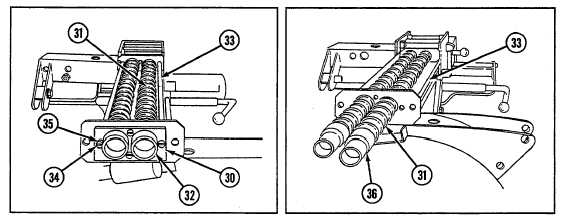
WARNING
Remove retaining strap (30) carefully to prevent
springs (31) from suddenly decompressing.
6 Remove retaining strap (30) and two retainers (32)
from support assembly (33) by removing four
screws (34) and four lockwashers (35).
7 Remove two guides (36) and two springs (31)
from support assembly (33).
9-127