CHAPTER 9: MAINTENANCE OF HULL- AND CAB-RELATED COMPONENTS
TM 9-2350-256-20
9-72 REPLACE/REPAIR STEERING CONTROLS AND LINKAGES
THIS TASK COVERS
a.
Removal
b.
Disassembly
c.
Assembly
d.
Installation
INITIAL SET-UP
Tools:
Equipment Conditions -Continued
Tool kit, general mechanic's (Appendix C, item 53)
Powerplant removed (see paragraph 3-1)
Pliers, retaining ring (Appendix C, item 30)
Left-side air cleaner removed (see
paragraph 4-24)
Parts:
Cab subfloor plates removed (see paragraphs 9-1
Bearings (4) (Appendix G, item 1)
through 9-23)
Lockwashers (28) (Appendix G, item 132)
Air inlet doors removed as necessary (see
Lockwasher (Appendix G, item 144)
paragraph 9-56)
Pin, cotter (Appendix G. item 212)
Air inlet grilles removed as necessary (see
Pin, cotter (Appendix G, item 227)
paragraph 9-57)
Seals (4) (Appendix G, item 249)
Ammunition rack removed (see paragraph 9-100)
Toolbox rack removed (see paragraph 9-103)
Oddment tray removed (see paragraph 9-104)
NOTE
Only remove or open items necessary to gain
access to area of linkage requiring removal.
a. REMOVAL
1
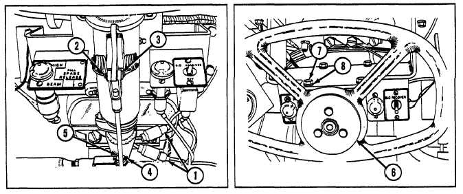
Disconnect two electrical leads (1).
2
Remove cotter pin (2) and straight pin (3).
3
Remove cotter pin (4) and straight pin (5).
4
Remove steering control assembly (6) by removing four screws (7) and four lockwashers (8).
5
Remove connecting link (9) by removing screw (10) and lockwasher (11).
6
Disconnect and remove two lubrication tubes (12 and 13), two elbows (14), two adapters (15), and two fittings (16).
9-146