CHAPTER 9: MAINTENANCE OF HULL- AND CAB-RELATED COMPONENTS
TM 9-2350-256-20
9-72 REPLACE/REPAIR STEERING CONTROLS AND LINKAGE S--Continued
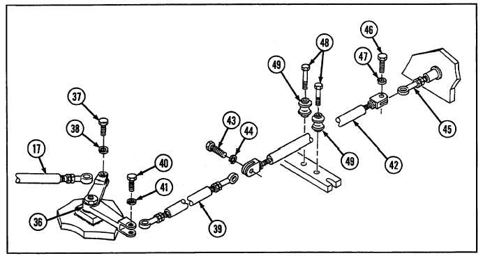
13 Remove connecting link (17) from bell crank assembly (36) by removing screw (37) and lockwasher (38).
14 Disconnect connecting link (39) from bell crank assembly (36) by removing screw (40) and lockwasher (41).
15 Remove connecting link (39) from tube assembly (42) by removing screw (43) and lockwasher (44).
16 Remove tube assembly (42) from rod end bearing (45) by removing screw (46) and lockwasher (47).
17 Remove six bolts (48) and six rollers (49).
18 Loosen nut (50) and unscrew rod end bearing (45) from connecting link (51). Remove nut.
19 Remove screw (52) and lockwasher (53).
20 Pry rubber bellows (54) loose from bulkhead (55) and pull connecting link (51) from bulkhead.
21 Remove rubber bellows (54) from connecting link (51) by removing clamp (56) and bushing (57).
22 Remove connecting links (58, 59, and 60) by removing screw (61) and lockwasher (62) from ends of each connecting
link
23 Remove two bell crank assemblies (63 and 64) from mounting brackets (65 and 66) by removing two retaining rings
(67 and 68), four lubrication fittings (69 and 70), and two grooved pins (71).
24 Remove two bell cranks (72 and 36) by removing lubrication fitting (73), bolt (74), lockwasher (75), and flat washer
(76) from each.
25 Remove screw (77), lockwasher (78), and lever (79).
9-148


