SECTION V: CONTROLS AND LINKAGES
TM 9-2350-256-20
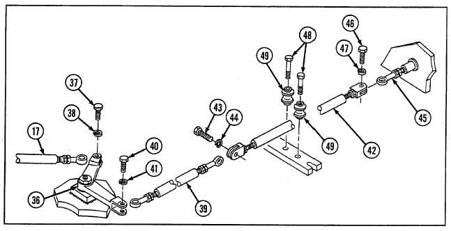
12 Install six rollers (49) with six bolts (48).
13 Install tube assembly (42) to rod end bearing (45) with new lockwasher (47) and screw (46).
14 Install connecting link (39) to tube assembly (42) with new lockwasher (44) and screw (43).
15 Connect connecting link (39) to bell crank assembly (36) with new lockwasher (41) and screw (40).
16 Install connecting link (17) to bell crank assembly (36) with new lockwasher (38) and screw (37).
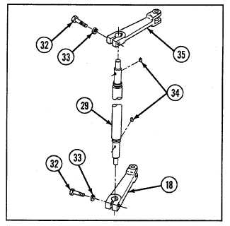
17. Install two levers (35 and 18) to shaft assembly (29)
with two keys (34), two new lockwashers (33), and two
screws (32).
9-153


