SECTION V: CONTROLS AND LINKAGES
TM 9-2350-256-20
d. INSTALLATION
1
Install mounting bracket (65) with three new lockwashers (85), flat washer (86), and three screws (84).
2
If removed, install two clevis assemblies (83) and two nuts (82) to tube assembly (42).
3
If removed, install bearing (81) and nut (80) to each end of connecting links (9, 17, 39, 51, 58, 59, and 60).
4
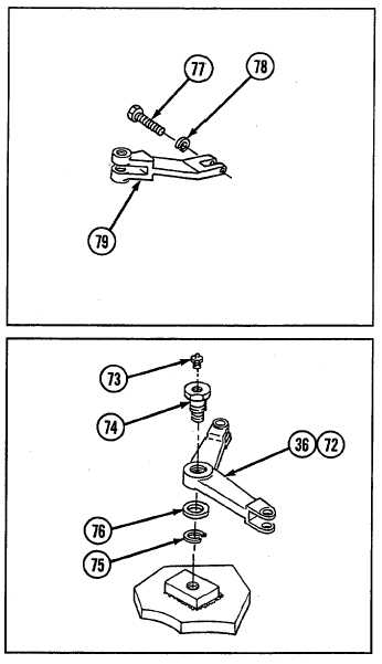
Install lever (79) with new lockwasher (78) and screw (77).
5
Install two bell cranks (72 and 36) each with lubrication
fitting (73), flat washer (76), new lockwasher (75), and
bolt (74).
6
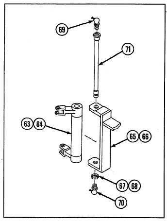
Install two bell crank assemblies (63 and 64) to
mounting brackets (65 and 66) with two grooved pins
(71), four lubrication fittings (69 and 70), and two
retaining rings (67 and 68).
9-151


