SECTION V: CONTROLS AND LINKAGES
TM 9-2350-256-20
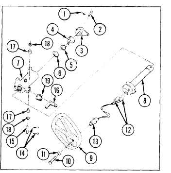
9-74 REPLACE/REPAIR STEERING CONTROL ASSEMBLY
THIS TASK COVERS
a. Removal
b. Disassembly
c. Assembly
d. Installation
INITIAL SET-UP
Tools:
Parts:
•Tool kit, general mechanic's (Appendix C, item 53)
•Lockwasher (3) (Appendix G, item 130)
•Pliers, retainig ring (Appendix C, item 30)
•Pin, cotter (Appendix G, item 227)
•Pins cotter (2) (Appendix G, item 210)
a. REMOVAL
Remove steering control assembly (see paragraph 9-72)
b. DISASSEMBLY
1
Remove cotter pin (1) and straight pin (2) from
control lever (3).
2
Remove control lever (3) with spring (4).
3
Remove retaining ring (5) and washer (6).
4
Pull housing assembly (7) from steering column (8).
5
Remove steering wheel (9) from steering column
(8) by removing three screw (10) and three
lockwasher (11).
6
Remove connectors (12) from horn switch assembly
(13) and pull horn switch assembly out of steering
column (8).
7 R e m o v e t w o c o t t e r p i n ( 1 5 ) b e l l c r a n k
(16), two spacers (17), two washers (18), and spring
(19) from housing assembly (7).
c. ASSEMBLY
1 Install spring (19), two washers (18), two spacers (17), bell crank (16), pin (15) and two new cotter pins (14 ) to
housing assembly, (7).
2
Pull horn switch assembly (13) wires through steering column (8). Install connectors (12) to horn switch
assembles.
3
Install steering wheel (1) to steering column (1) with three screws (10) and three new lockwashers, (11)
4
Install steering column (8) to housing assembly (7)
5
Install washer (6), retaining ring (5), spring (4), and control lever (3).
6
Install straight pin (3) and new cotter pin (1).
d. INSTALLATION
Install steering control assembly (see paragraph 9-72).
9 - 1 5 7