CHAPTER 9: MAINTENANCE OF HULL-AND CAB-RELATED COMPONENTS
TM 9-2350-256-20
9-76
REPLACE/REPAIR SHIFTING CONTROLS AND LINKAGES-Continued
15
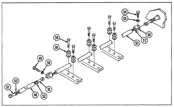
Remove tube assembly (48) by removing screw (49) and lockwasher (50). Remove bearing (51) and nut (52) from
each end of tube assembly.
16
Remove tube assembly (53) by removing screw (54) and lockwasher (55). Remove bearing (56) and nut (57) from
each end of tube assembly.
17
Remove six bolts (58) and six rollers (59).
18
Remove screw (60) and lockwasher (61).
19
Loosen nuts (62) and unscrew rod end bearings (63) from tube assembly (64). Remove nuts from each end of
tube assembly.
20
Pry rubber boot (65) from bulkhead (66) and pull tube assembly (64) from bulkhead.
21
Remove rubber boot (65) from tube assembly (64) by removing clamp (67) and bushing (68).
22
Remove tube assemblies (69, 70, and 71) by removing screw (72) and lockwasher (73) from ends of each tube
assembly.
23
Remove bearing (74) and nut (75) from each end of tube assemblies (69, 70, and 71).
24
Remove two bell crank assemblies (76) from mounting brackets (77 and 78) by removing two retaining rings (79),
four lubrication fittings (80 and 81), and two grooved pins (82).
9-162