TM 9-2350-256-20
CHAPTER 9: MAINTENANCE OF HULL- AND CAB-RELATED COMPONENTS
9-76 REPLACE/REPAIR SHIFTING CONTROLS AND LINKAGES-Continued
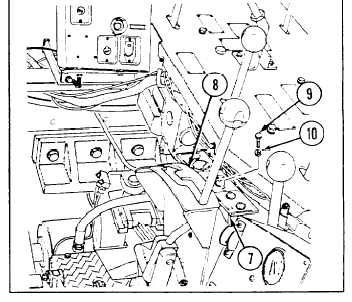
23 Install warning indicator light, gage, and flasher
system panel (7) to transmission shift control
assembly (8) with two new lockwashers (10) and
two screws (9).
24 Install electrical leads to warning indicator light,
gage, and flasher system panel (7) (see paragraph
6-26) attached to transmission shift control
assembly (8).
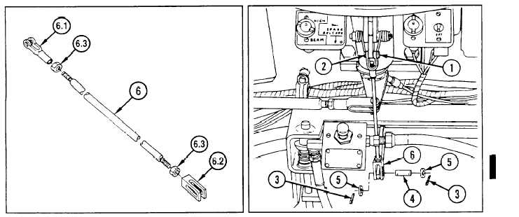
24.1 Install two nuts (6.3) and two clevis (6.1 and 6.2)
to rod (6).
NOTE
Be sure that rod (6) is installed with clevis
(6.2) at bottom of rod (6).
25
Install rod (6), two washers (5), straight pin (4), and
two new cotter pins (3).
26
Install straight pin (2) and new cotter pin (1).
NOTE
Follow-on maintenance:
Only install or close items necessary to gain access to area of linkage
requiring removal.
•Install oddment ray (see paragraph 9-104)
•Install toolbox rack (see paragraph 9-103)
•Install ammunition rack (see paragraph 9-100)
•Install air inlet grilles if removed (see paragraph 9-57)
•Install air inlet doors if removed (see paragraph 9-56)
•Install cab subfloor plates (see paragraphs 9-1 through 9-23)
•Install left-side air cleaner (see paragraph 4-24)
*Install powerplant (see paragraph 3-1)
9 - 1 7 0
Change 1