TM 9-2350-256-20
CHAPTER 9: MAINTENANCE OF HULL- AND CAB-RELATED COMPONENTS
9-78 REPLACE/REPAIR/SERVICE ACCELERATOR CONTROLS AND LINKAGES
THIS TASK COVERS
a. Removal
b. Disassembly
c. Cleaning d . I n s p e c t i o n
e. Repair
f. Assembly
g. Installation
INITIAL SET-UP
Tools:
Equipment Conditions-Continued
•Tool kit, general mechanic’s (Appendix C, item 53)
•Powerplant removed (see paragraph 3-1)
*File, thread restorer (Appendix C, item 13)
•Left-side air cleaner removed (see paragraph 4-24)
•Cab subfloor plates removed (see paragraphs 9-1
Parts:
through 9-23)
•Lockwashers (7) (Appendix G, item 130)
•Air inlet doors removed as necessary (see
•Lockwashers (13) (Appendix G, item 132)
paragraph 9-56)
•Pins, cotter (3) (Appendix G, item 216)
•Air inlet grilles removed as necessary (see
paragraph 9-57)
Equipment Conditions:
•Ammunition rack removed (see paragraph 9-100)
•Toolbox rack removed (see paragraph 9-103)
NOTE
•Oddment tray removed (see paragraph 9-104)
Only remove or open items necessary to gain
access to area of linkage requiring removal.
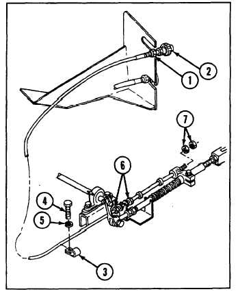
a. REMOVAL
1 Loosen self-locking nut (1) on throttle control
assembly (2).
2 Remove clamp (3) by removing screw (4) and
lockwasher (5).
3
Loosen two self-locking nuts (6).
4
Remove two nuts (7) and throttle control assembly
(2).
9-172