SECTION I: MAIN WINCH ASSEMBLY
TM 9-2350-256-20
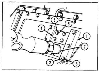
5
Install two retainers (4) and two halfbushings (7)
each with four screws (5) and four new
lockwashers (6).
6
Install two guides (1) each with four screws (2) and
four new lockwashers (3).
WARNING
Gloves should be worn when working
with cable to prevent cuts and abrasions.
7
Run winch slowly and guide cable on drum (12).
Apply load to cable from outside of vehicle to
prevent loose cable wrap.
SECTION II: HOIST WINCH ASSEMBLY
Para.
Task
Page
11-6
Replace Hoist Winch Hose and Cable Assembly.....................................................................................11-9
11-7
Service Hoist Winch Brake Band Adjustment....................................................................................... 11-10
11-8
Replace Hoist Winch Manual Control and Linkage ............................................................................... 11-11
11-6 REPLACE HOIST WINCH HOSE AND CABLE ASSEMBLY
THIS TASK COVERS
a. Removal
b. Installation
INITIAL SET-UP
Tools:
Equipment Conditions:
Tool kit, general mechanic's (Appendix C, item 53)
Hoist winch cable access door opened (see
paragraph 9-4)
Material:
Cable paid out (refer to TM 9-2350-256-10)
Grease, GAA (Appendix D, item 13)
Floor plates door opened (see Chapter 9, Section I)
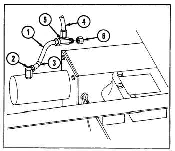
a. REMOVAL
1
Disconnect hose (1) from elbow (2), and remove
two band markers (3) from hose.
2
Remove hoses (1 and 4) from tee (5).
3
Remove tee (5) and seal (6).
11-9