SECTION II: HOIST WINCH ASSEMBLY
TM 9-2350-256-20
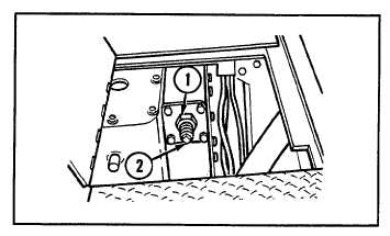
ADJUSTMENT
1
Loosen locknut (1).
2
Tighten
adjusting
screw
(2)
clockwise
to
maximum, then back adjusting screw off 1 full
turn. Hold adjusting screw in position and tighten
locknut (1).
NOTE
Follow-on maintenance:
Close U-35 winch center
right floor plate (see
paragraph 9-4)
11-8 REPLACE HOIST WINCH MANUAL CONTROL AND LINKAGE
THIS TASK COVERS
a. Removal
b. Installation
INITIAL SET-UP
Tools:
Parts:
Equipment Condition:
Tool kit, general mechanic's
Nut, self-locking
Stowage basket forward
(Appendix C, item 53)
(Appendix G, item 173)
intermediate left floor plate
Pins, cotter (4)
removed (see paragraph 9-21)
(Appendix G, item 212)
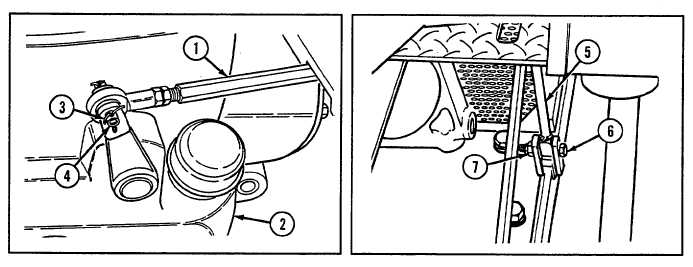
a. REMOVAL
1
Disconnect control rod (1) from hoist winch (2) by removing two cotter pins (3) and straight pin (4).
2
Remove control lever (5) by removing screw (6) and self-locking nut (7).
11-11