CHAPTER 2: VEHICLE MAINTENANCE INSTRUCTIONS
TM 9-2350-256-20
2-19 ELECTRICAL TROUBLESHOOTING-Continued
APU GENERATOR SYSTEM (DUAL VOLTAGE)--Continued
WARNING
Remove all jewelry such as rings, dog
tags, bracelets, etc. If jewelry contacts
a metal surface a direct short may result
in instant heating of tools, damage to
equipment, and injury or death to
personnel.
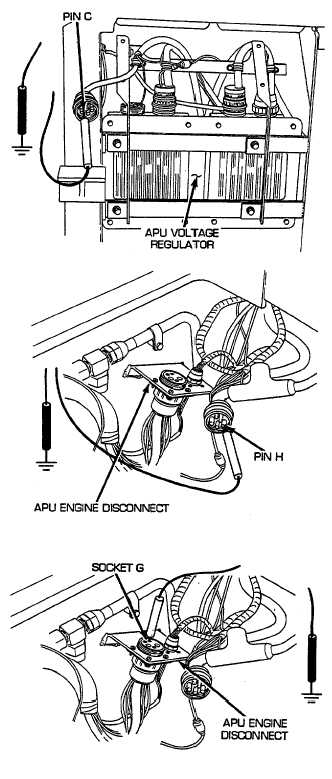
D Place red lead of multimeter on pin C of wire 478A and
black lead to ground. Turn MASTER and APU GEN
switches ON, start APU, and check for voltage. Turn
MASTER and APU GEN switches OFF. If voltage is not
present, replace APU regulator (see paragraph 6-5). If
voltage is present, go to step E.
E Reconnect bulkhead to APU, master relay, and rigger's
lights wiring harness to APU regulator. Open center-
front air inlet doors (TM 9-2350-256-10). Disconnect
bulkhead to APU, master relay, and rigger's lights wiring
harness from APU engine disconnect. Place red lead of
multimeter on pin H of wire 478A. Turn MASTER and
APU GEN switches ON and check for voltage. Turn
MASTER and APU GEN switches OFF. If voltage is not
present, repair/replace wire 478A of bulkhead to APU,
master relay, and rigger's lights wiring harness (see
paragraph 6-75). If voltage is present, go to step F.
F Reconnect bulkhead to APU, master relay, and rigger's
lights wiring harness to APU regulator. Disconnect
bulkhead to APU, master relay, and rigger's lights wiring
harness from APU engine disconnect. Place red lead of
multimeter in socket G of wire 62 and black lead to
ground. Turn MASTER and APU GEN switches ON and
check for voltage. Turn MASTER and APU GEN
switches OFF. If voltage is present, go to step G. If
voltage is not present, repair/replace wire 62 of
bulkhead to APU, master relay, and rigger's lights wiring
harness (see paragraph 6-75).
2-140