TM 9-2350-256-20
CHAPTER 3: MAlNTENANCE OF ENGINE
3-9
REPLACE OIL PAN RELATED PARTS
THIS TASK COVERS
a. Removal
b. Installation
INlTlAL SET-UP
Tools
Part:
Tool kit, general mechanic’s
Gasket (Appendix G, item 77)
(Appendix C, item 53)
Equipment Condition:
Powerplant removed (see
paragraph 3-1)
Place container with minimum capacity of
25 gallons (95 liters) under oil pan before
beginning procedure.
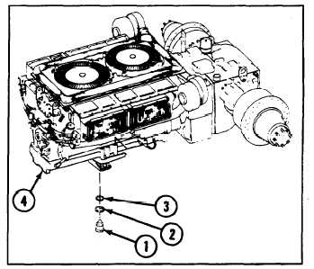
a. REMOVAL
Remove plug (1), gasket (2), and ring (3) from oil pan
(4).
b. INSTALLATION
Install ring (3), gasket (2), and plug (1) to oil pan (4).
NOTE
Follow-on maintenance:
Install power-plant (see
paragraph 3-1)
3-10 REPLACE CRANKCASE BREATHER TUBE
THIS TASK COVERS
a. Removal
b. Installation
INITIAL SET-UP
T o o l s :
Tool kit, general mechanic’s
(Appendix C, item 53)
Parts:
Gasket (Appendix G, item 53)
Gaskets (2) (Appendix G,
item 54)
Parts-Continued:
Equipment Conditions:
Lockwashers (2) (Appendix G,
Powerplant removed (see
item 100)
paragraph 3-1)
Nuts, self-locking (3)
Exhaust doors opened (see
(Appendix G, item 166)
paragraph 9-61)
Transmission access door
opened (see paragraph 9-55)
a. REMOVAL
1 Remove tube (1) by removing hose clamps (2) from each end.
2 Remove air duct hose (3) by removing hose clamp (4).
3 Remove air duct hose (5) by removing hose clamp (6).
4 Remove self-locking nut (7), washer (8), and loop clamp (9).
5 Remove tube (10) by removing hose clamps (11) from each end.
6 Remove air duct hose (12) by removing hose clamp (13).
3-26