TM 9-2350-256-20
3-7
REPLACE OIL LEVEL INDICATOR AND RELATED PARTS
THIS TASK COVERS
a. Removal
b. Installation
INITIAL SET-UP
Tools:
Tool kit, general mechanic’s (Appendix C, item 53)
Parts-Continued:
Packings, preformed (2) (Appendix G, item 200)
Parts:
Drivescrews (2) (Appendix G, item 15)
Gasket (Appendix G, item 26)
Gasket (Appendix G, item 69)
Lockwashers (2) (Appendix G, item 100)
Nuts, self-locking (3) (Appendix G, item 166)
Reference:
TM 9-2350-256-10
Equipment Conditions:
Power-plant removed (see paragraph 3-1)
Engine oil drained
a. REMOVAL
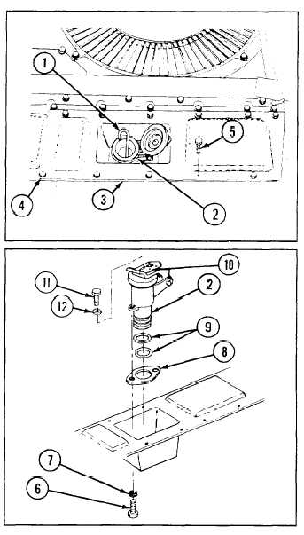
1 Remove oil level gage rod (1).
NOTE
Oil level indicator tube cap assembly (2) is
removed with right front upper cover (3).
2 Remove right front upper cover (3) and strap (4) by
removing 12 screws (5).
3 Remove oil level indicator tube cap assembly (2)
from right front upper cover (3) by removing two
screws (6) and two lockwashers (7).
4 Remove gasket (8) and two preformed packings (9)
from oil level indicator tube cap assembly (2).
5 Remove ID plate (10) by removing two drivescrews
(11) and two flat washers (12).
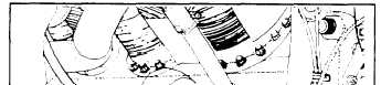
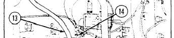
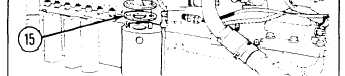
6 Remove oil level indicator tube (13) by removing
three self-locking nuts (11) and gasket (15).
Change 1
3-23