CHAPTER 6: MAINTENANCE OF ELECTRICAL SYSTEMS AND CIRCUITS
TM 9-2350-256-20
6-8 REPLACE/REPAIR GAGE PANEL ASSEMBLY-Continued
b. DISASSEMBLY
1
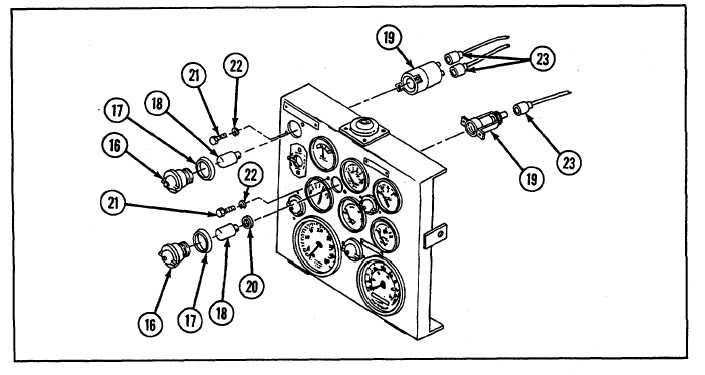
Unscrew and remove five light lenses (16) with five preformed packings (17).
2
Remove five lamps (18) from indicator lights (19) by depressing and turning counterclockwise.
NOTE
Gaskets (20) are present on three of the lamps (18).
3
Remove three gaskets (20).
4
Remove five indicator lights (19) by removing two screws (21) and two lockwashers (22) from each.
NOTE
Identify connectors upon removal to ensure proper installation.
5
Disconnect connectors (23) from five indicator lights (19).
NOTE
Battery generator indicator meter (24) has only one connector.
6
Disconnect connector (25) from battery generator indicator meter (24) and two connectors (26) from engine oil
temperature gage (27), engine oil pressure gage (28), fuel tank level gage (29), transmission oil temperature
gage (30), and transmission oil pressure gage (31).
6-20

