SECTION V: VEHICLE WIRING
TM 9-2350-256-20
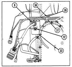
11 Disconnect two connectors (9 and 12) from APU
starter relay (33).
12 Remove two clamps (37) by removing two screws
(38) and two washers (39).
b. DISASSEMBLY
Disassemble wiring harness (see Chapter 6, Section VII).
c. ASSEMBLY
Assemble wiring harness (see Chapter 6, Section VII).
d. INSTALLATION
1 Install two clamps (37) using two screws (38) and
two washers (39).
2 Connect lead (13) to APU generator (31) using
three new lockwashers (36) and nut (35).
3 Connect two leads (10 and 11) to APU generator (31) using two nuts (34).
4 Connect two connectors (9 and 12) to APU starter relay (33).
5 Connect lead (8) to APU generator (31) using nut (32).
6 Connect lead (7) to preheat solenoid (20) using four lockwashers (27) and nut (26).
7 Connect lead (6) to preheat solenoid (20) using four lockwashers (27) and nut (26).
8 Connect lead (5) from fuel shutoff solenoid (23) using washer (25) and nut (24).
9 Connect lead (4) to preheat solenoid (20) using washer (22) and nut (21).
10 Connect lead (3) to diode assembly (16) using screw (17), new lockwasher (18), and nut (19).
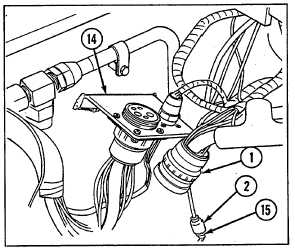
11 Connect connector (2) to bulkhead to APU, master
relay, and rigger's lights wiring harness (15).
12 Connect connector (1) to APU engine disconnect
bracket (14).
NOTE
Follow-on maintenance
Install APU access
cover assembly (see
paragraph 9-49)
6-211