CHAPTER 7: MAINTENANCE OF TRANSMISSION AND OUTPUT REDUCTION DRIVES
TM 9-2350-256-20
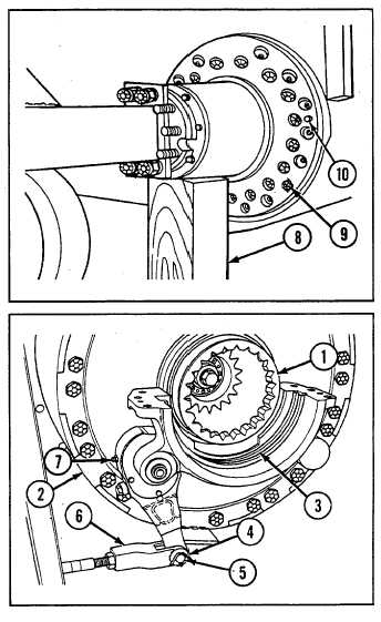
7-9 REPLACE TRANSMISSION OUTPUT REDUCTION DRIVES AND DRIVE COUPLINGS-Continued
7
Install 19 new self-locking bolts (9). Torque self-locking
bolts to 337-385 lb-ft (457-522 Nom).
8
Remove two jackscrews (10).
9
Remove wooden block (8).
10 Connect brake rod (6) using straight pin (5) and new
cotter pin (4).
11 Install lubrication fitting (7), if necessary.
NOTE
Output reduction drive alignment ring (3) is
installed in right-side output reduction drive
(2) only.
12 Install output reduction drive alignment ring (3) in
output reduction drive (2).
13 Install drive coupling (1) on output reduction drive
(2).
NOTE
Follow-on maintenance:
• Install final drive hub
and sprockets (see
paragraph 8-10)
• Install powerplant
(see paragraph 3-1)
7-14