SECTION I: WHEELS AND TRACKS
TM 9-2350-256-20
3
Install and block roadwheel arm (see paragraph
8-3).
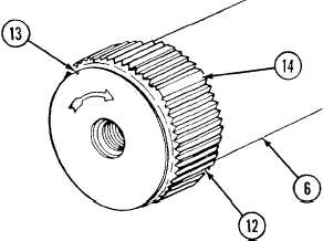
4
Install torsion bar (6) using adapter and puller as
follows:
Coat serration (12) on both ends of torsion bar with
GAA grease (see Appendix J). Screw adapter into
tapped holes in end of torsion bar. Screw puller
into tapped hole in adapter. Hold torsion bar so
that V-notch (13) cut into chamfer on outer end is
at top. Slide torsion bar in and rotate until blank
serration (14) in inner end of torsion bar (opposite
V-notch) aligns with blank serration in torsion bar
anchor (10). Push torsion bar in far enough to
engage torsion bar anchor. Turn roadwheel arm
(3) in direction of arrow on torsion bar until blank
serration (adjacent to V-groove) in outer end of
torsion bar aligns with blank serration in arm
(opposite V-groove in arm). Push bar in as far as it
will go. Pack cavity in roadwheel arm with grease
(see Appendix J).
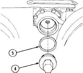
5
Install torsion bar end plug (4) and new gasket (5)
using wrench plug.
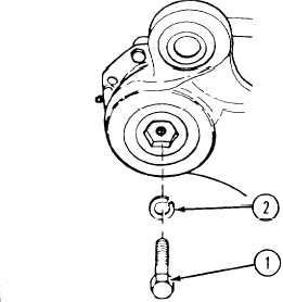
6
Install screw (1) and new lockwasher (2). Torque
screw to 75-100 lb-ft (102-136 N•m).
NOTE
Follow-on maintenance: •Connect shock
absorber (see
paragraph 8-12)
•Connect idler link (see
paragraph 8-8)
•Install roadwheel (see
paragraph 8-1)
Change 1
8-5