SECTION I: WHEELS AND TRACKS
TM 9-2350-256-20
8-4 REPLACE/SERVICE ROADWHEEL HUB ASSEMBLY
THIS TASK COVERS
a. Removal/Disassembly
b. Cleaning
c. Inspection
d. Assembly/Installation
INITIAL SET-UP
Tools:
Material/Parts:
Tool kit, general mechanic's (Appendix C,
Solvent, dry-cleaning (Appendix D, item 9)
item 53)
Gaskets (6) (Appendix G, item 48)
Handle (Appendix C, item 18)
Gaskets (6) (Appendix G, item 49)
Multiplier torque (Appendix C, item 27)
Lockwashers (84) (Appendix G, item 132)
Remover and replacer (Appendix C, item 38)
Lockwashers (6) (Appendix G, item 134)
Socket set (Appendix C, item 48)
Wrench, socket (Appendix C, item 57)
Personnel Required:
Wrench, torque, 0-175 lb-ft (0-237 N m)
Two
(Appendix C, item 61)
Wrench, torque, 0-600 Ib-ft (0-813 N m)
Equipment Conditions:
(Appendix C, item 63)
Roadwheel removed (see paragraph 8-1)
Track tension loosened (refer to
TM 9-2350-256-10)
NOTE
The following procedures are the same for all six roadwheel hub assemblies.
a. REMOVAL/DISASSEMBLY
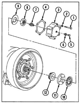
1 Remove six screws (1), six lockwashers (2), access
cover (3), and gasket (4).
2 Remove relief valve (5), bushing (6), and static
grounding spring (7).
3 Remove nut (8), lockplate (9), ring (10), and
adjusting nut (11).
4 Remove outer cone bearing (12).
8-9