TM 9-2350-256-34-1
3-57.
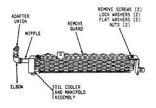
Mechanical
Transmission
Oil
Cooler
Assembly.
a.
Removal.
Refer
to
paragraph
2-33
for
instructions on removal and installation.
b.
Disassembly. Disassemble the oil
cooler
assembly as shown in figure 3-23.
c.
Cleaning. Clean dirt and other foreign material
from all parts with drycleaning solvent or mineral spirits
paint thinner, followed by wire brushing where necessary.
Dry with compressed air.
d.
Inspection and Repair.
(1)
Inspection.
(a)
Inspect
oil
cooler
for
cracks,
distortion, breakage, and other damage that might cause
leakage or otherwise impair its use.
(b)
Inspect threaded parts for nicks,
cross threading, and other evidence of excessive wear.
(c)
Inspect guard assembly for broken
welds, cracks, and other damage that would impair its
use.
(2)
Repair. Replace any parts that are
defective.
e.
Assembly.
Assemble
the
mechanical
transmission oil cooler assembly in reverse order of
disassembly.
3-58.
Mechanical Transmission and Main Hydraulic
Pump Assembly
a.
Removal. Refer to paragraph 2-32 for removal
and installation instructions.
b.
Repair. Refer to TM 9-2350-256-34-2 for
inspection and repair instructions.
3-59.
Hoist Winch Assembly
a.
Removal. Refer to paragraph 2-35 for removal
and installation instructions.
b.
Repair. Refer to TM 9-2350-256-34-2 for
inspection and repair instructions.
3-60.
Main
and
Hoist
Winch
Brake
Band
Assemblies
a.
Removal. Refer to paragraph 2-39 for removal
and installation instructions.
b.
Disassembly. Disassemble the brake band
assembly as shown in figure 3-24.
Figure 3-23. Mechanical transmission oil cooler
assembly-disassembly and assembly.
c.
Cleaning. Clean dirt and other foreign material
from all parts with drycleaning solvent or mineral spirits
paint thinner, followed by wire brushing where necessary.
Dry with compressed air.
3-44 CHANGE 7