TM 9--2350--292--20--1
0244 00--8
PTO/ACCESSORY PANEL REPAIR -- CONTINUED
0244 00
Assembly--Continued
NOTE
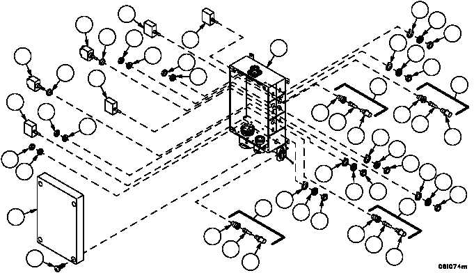
There are four indicator light assemblies on the
PTO/accessory panel. All four are assembled and
installed in the same manner. Perform steps 14 and 15
to assemble and install these light assemblies.
14. Install LED (24) and lens (23) in socket (25).
15. Install indicator light holder (22) on enclosure (10) with lockwasher (21) and nut (20).
16. Install two toggle switches (19) and two switch boots (18) in enclosure (10) with two key washers (17), two lock-
washers (16) and two nuts (15).
17. Install four toggle switches (14) in enclosure (10) with four key washers (13), four lockwashers (12) and four nuts (11).
18. Install PTO/accessory panel’s internal wiring in accordance with Electrical Schematic (FP--17) into enclosure (10),
using new electrical tiedown straps as required to secure wiring in place.
19. Install cover (9) on enclosure (10) with four screws (8).
8
9
20
21
14
20
21
19
18
14
19
18
20
21
20
21
14
14
10
23
24
25
22
13
12
11
25
24
23
17
16
15
22
11
12
13
15
16
17
23
24
25
22
25
24
23
22
11
12
13
13
12
11