TM 9--2350--292--20--1
BILGE PUMP OVERVIEW AND DIAGRAMS.
0029 00
THIS WORK PACKAGE COVERS:
Bilge Pump Overview and Diagrams
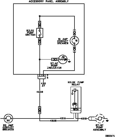
The bilge pump system consists of the bilge pump, bilge pump relay, BILGE PUMP switch, BILGE PUMP indicator,
a 15--amp circuit breaker, a 50--amp circuit breaker, and related electrical wiring.
When the MASTER switch is ON, the bilge pump operates and the BILGE PUMP indicator lights whenever the
BILGE PUMP switch is turned ON. With the BILGE PUMP switch ON, system power (+24 -- 28 V dc) is supplied
through the 15--amp circuit breaker and BILGE PUMP switch to energize the bilge pump relay. With the relay ener-
gized, system power is now supplied through the 50--amp circuit breaker and relay contacts as operating voltage
for the bilge pump. System power is also supplied to light the BILGE PUMP indicator while the bilge pump is in
operation,
The diagram below shows the relationship of the bilge pump system components.
END OF TASK
0029 00--1/2 blank