TM 9--2350--292--20--1
0096 00--4
AUXILIARY WINCH FAILS TO OPERATE OR DEVELOP FULL POWER --
CONTINUED
0096 00
H
Are both gauge readings between 3900--4100 psi?
CONTINUED FROM STEP G
no
yes
CONTINUED ON NEXT PAGE
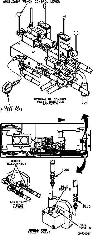
1. Remove hydraulic control valve manifold
assembly shields (WP 0519 00).
2. Install a 0--5000 psi dial pressure gauge in test
port P of the hydraulic control valve manifold
assembly.
3. Disconnect the quick--disconnects of the
auxiliary winch hoses.
4. Disconnect hoses from ports A and B of cross
port relief valve and plug hoses and ports A
and B.
5. Start main engine and set speed to 1800 rpm
(TM 9--2350--292--10).
6. Start main hydraulic system
(TM 9--2350--292--10).
7. Place the auxiliary winch control lever to the
PAYOUT position. Record gauge reading.
8. Place the auxiliary winch control lever to the
PAYIN position. Record the gauge reading.
9. Shut down hydraulics and main engine
(TM 9--2350--292--10).
Replace cross port relief
valve (WP 0560 00).
Verify fault is corrected.
FORWARD
WARNING