TM 9--2350--292--20--1
0100 00--3
HOIST WINCH FAILS TO OPERATE OR DEVELOP FULL POWER --
CONTINUED
0100 00
CONTINUED FROM STEP E
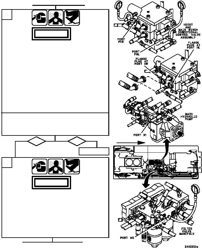
1. Remove hoses from split flanges at ports HR and
HL of hoist and main winch directional control valve
assembly.
2. Install 1--inch flange plugs with o--ring in ports HR
and HL, and secure plugs with split flanges.
3. Install 0--5000 psi dial pressure gauge in the MS
port of the filter valve manifold.
4. Install 0--5000 psi dial pressure gauge with 3/8--inch
tee between port X1 of front pump on main
hydraulic pump assembly and attaching hose.
CONTINUED ON NEXT PAGE
F
When in raise position was pressure at PHR port
385--470 psi, and was pressure at PHL port less than
50 psi; and when in lower position, was pressure at
PHL port 385--470 psi, and was pressure at PHR port
less than 50 psi?
no
yes
1. Install 0--4000 psi testing gauge assembly with
1/4--inch tee between port PHR on hoist and main
winch directional control valve assembly and
attaching hose.
2. Install 0--4000 psi testing gauge assembly with
1/4--inch tee between port PHL on hoist and main
winch directional control valve assembly and
attaching hose.
3. Start main engine, energize hydraulics, and set
engine speed to 1800 rpm (TM 9--2350--292--10).
4. Place hoist control valve lever in lower position and
record gauge pressures.
5. Place hoist control valve lever in raise position and
record gauge pressures.
6. Shut down hydraulics and main engine
(TM 9--2350--292--10).
Go to Step H.
G
FORWARD
WARNING
WARNING