TM 9--2350--292--20--2
0553 00--2
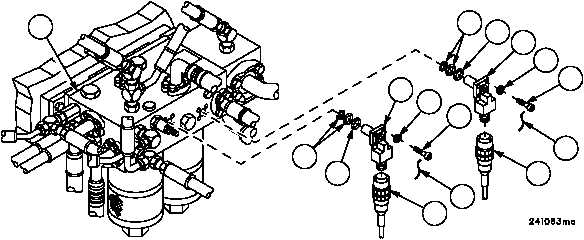
HYDRAULIC FILTER MANIFOLD RETURN CIRCUIT OR CHARGE CIRCUIT
INDICATOR SWITCH REPLACEMENT -- CONTINUED
0553 00
Removal--Continued
WARNING
2. Remove nonelectrical wire (5), four screws (6), four flat washers (7), return circuit indicator switch (2) or charge
circuit indicator switch (4), two preformed packings (8) and retainer packing (9) from filter manifold (10). Discard
nonelectrical wire, preformed packings and retainer packing.
3. Inspect parts for damage and replace as required.
Installation
1. Apply a thin coat of lubricant to two new preformed packings (8) and new retainer packing (9).
2. Apply sealing compound to threads of four screws (6).
3. Install return circuit indicator switch (2) or charge circuit indicator switch (4) with two new preformed packings (8)
and new retainer packing (9) on filter manifold (10) with four screws (6) and four flat washers (7). Torque screws
(6) to 17--19 lb--in. (1.9--2.1 NSm). Install new nonelectrical wire (5).
4. Connect wiring harness 2W601 connector P3 (1) to return circuit indicator switch (2) or connect wiring harness
2W601 connector P4 (3) to charge circuit indicator switch (4).
Figure 300
2
1
5
3
5
8
7
6
6
7
4
8
9
9
10
NOTE
FOLLOW--ON MAINTENANCE:
Connect battery power (WP 0256 00)
Install subfloor plate #22 (WP 0454 00)
Start engine, pressurize hydraulic system
(TM 9--2350--292--10)
Stow boom (TM 9--2350--292--10)
Lock spade (TM 9--2350--292--10)
END OF TASK