TM 5-4240-501-148P
CARBURETION
Vacu-Jet, Pulsa-Jet
Model Series 82500, 92500 and 94500 engines should
be adjusted with fuel tank half full of gasoline.
Initial Adjustment: Turn needle valve clockwise to close
it. Then open 11/2 turns. This initial adjustment will
permit the engine to be started and warmed up before
making final adjustment.
Final Adjustment: Place governor speed control lever in
"FAST" position. Turn needle valve in until engine
misses (clockwise lean mixture) then turn it out past
smooth operating point until engine runs unevenly (rich
mixture). Now turn needle valve to the midpoint between
rich and lean so the engine runs smoothly. Next, adjust
idle RPM. Rotate throttle counterclockwise and hold
against stop. Adjust idle speed adjusting screw to obtain
1750 RPM. Release throttle engine should accelerate
without hesitation or sputtering. If engine does not
accelerate properly, the carburetor should be re-
adjusted, usually to a slightly richer mixture.
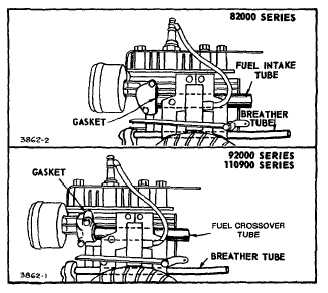
Breather and Fuel Intake Tubes
Breather tube and fuel intake tube thread into the
cylinder on Model Series 82000. Fuel intake tube is
bolted to the cylinder on Model Series 92000, 94000,
110900 and 111900. See Fig. 38. Check for good fit or
damaged gaskets to prevent air leaks or entry of dirt.
Fig. 38 - Breather and Fuel Intake Tubes
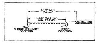
Choke-A-Matlc Adjustment
The Choke-A-Matic feature was standard on Model
Series 82000, 92500 (type nos. lower than 0600) 92900
(type nos. lower than 0500) engines. The remote control
must be of the type in which the control wire moves out
of the casing, when the control lever is moved from the
stop position to the "Choke" or "Start" position. A
minimum travel of 1-3/8" (34.9 mm) is required when the
! remote control is’ mounted, Fig. 39.
Fig. 39- Remote Control
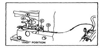
To install remote control assembly proceed as follows:
Remove the air cleaner and move the control lever to a
position about midway between idle and fast. Then
mount the remote control -with the casing clamp as
shown in Fig. 40.
Place control lever on equipment in fast (high speed)
position.
CONTROL
MUST
BE
MOUNTED
ON
EQUIPMENT
TO
MAKE
AN
ACCURATE
ADJUSTMENT. Lever "A" on carburetor should be just
touching choke shaft at "B." Move casing "D" forward or
backwards until correct position is obtained. Tighten
screw
"C."
Recheck
operation
of
controls
after
adjustment, Fig. 40.
Fig. 40 - Choke-A-Matic Control (Typical)
13