TM 5-4240-501-148P
CARBURETION
PULSA-JET
Choke-A-Matic Linkage
Disassembly (Except Model 100900, 130900)
To remove choke link, remove speed adjustment lever
and stop switch insulator plate. Remove speed
adjustment lever from choke link then pull out choke link
through hole in choke slide. Fig. 52.
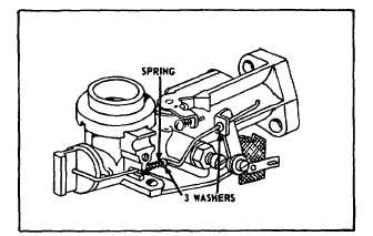
Fig. 52 - Choke-A-Matic Linkage
Repair
Replace worn or damaged parts. To assemble, slip
washers and spring over choke link. Fig. 53. Hook
choke link through hole in choke slide. Place other end
of choke link through hole in speed adjustment lever and
mount lever and stop switch insulator plate to carburetor.
Fig. 53 - Choke-A-Matic Linkage
Adjust Choke-A-Matic Linkage
The following covers Choke-A-Matic parts installed as a
part of the carburetor assembly. See Section 4 for
Choke-A-Matic remote controls.
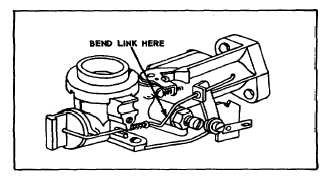
To check operation of Choke-A-Matic linkage, move
speed adjustment lever to choke position. If choke slide
does not fully close, replace link or use fiat nose pliers to
bend choke link. Fig. 54 (Do not overbend.) Speed
adjustment lever must make good contact against stop
switch when moved to stop position.
Fig. 54 - Adjust Choke Link
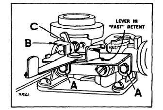
Choke-A-Matic Linkage Model 100900, 130900 and
131900
Manual or remote control for choke and stop is made by
a lever on the control plate mounted to carburetor by two
screws "A", Fig. 55. Lever for remote control has a loose
fit, for manual control, a friction fit. To check lever
action, move to left until it snaps into run detents. Lever
"B" should just touch choke lever at "C."
If it does not, loosen screws "A" slightly and move control
plate to right or left until lever just touches choke lever at
"C." Tighten screws.
Fig. 55 - Choke-A-Matic Linkage Model 100900, 130900,
131900
16