TM 5-4240-501-148P
CARBURETION
Vacu-Jet
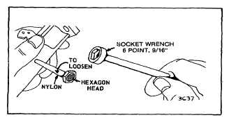
Fig. 64 - Replacing Nylon Fuel Pipe
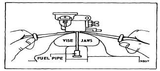
Fig. 65 - Removing Brass Fuel Pipe
To install brass fuel pipes, remove the throttle, if
necessary, and place the carburetor and pipe in a vise.
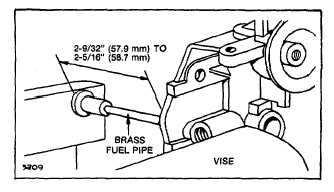
Press the pipe into the carburetor until it projects 2-9/32"
(57.9 mm) to 2-5/16" (58.7 mm) from carburetor gasket
surface. Fig. 66.
Fig. 66 - Replacing Brass Fuel Pipe
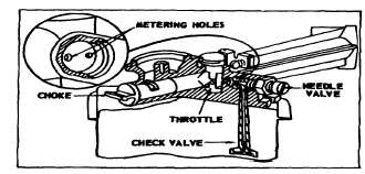
Needle Valve and Seat
Remove needle valve assembly to inspect. If carburetor
is gummy or dirty, remove seat to allow better cleaning of
metering holes. CAUTION: Do not change metering hole
sizes. Fig. 67.
Fig. 67 - Metering Holes
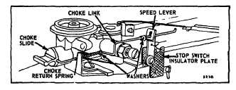
Choke-A-Matic Linkage
Disassemble
To remove choke link, remove speed adjustment lever
and stop switch insulator plate. Work link out through
hole in choke slide. Fig. 68.
Fig. 68 - Choke-A-Matic Linkage
Repair
Replace worn or damaged parts. To assemble
carburetor using choke slide, Fig. 68, place choke return
spring and three washers on choke link. Push choke link
through hole in carburetor body, turning link to line up
with hole in choke slide. Speed adjustment lever screw
and stop switch insulator plate should be installed as one
assembly after placing choke link through end of speed
adjustment lever.
Adjust Choke-A-Matic Linkage
The following covers Choke-A-Matic parts installed on
and as a part of the carburetor assembly. See Section 4
for Choke-A-Matic remote controls. To check operation
of Choke-A-Matic linkage, move speed adjustment lever
to CHOKE position. If choke slide does not FULLY
close, bend choke link. Fig. 69. Speed adjustment lever
must make good contact against stop switch.
19