TM 5-4240-501-148P
CARBURETION
Vacu-Jet
VACU-JET CARBURETORS
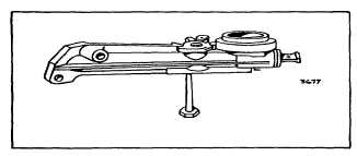
Fig. 59 - Vacu-Jet Carburetor
Carburetor and Tank Assembly
Remove the carburetor and fuel tank as one unit, being
careful not to bend the governor linkage or spring. On
models equipped with a stop switch, remove the ground
wire. After removal of the carburetor from the fuel tank,
inspect the tank for deposits of dirt and/or varnish and
mounting surfaces. Tank should be cleaned in solvent.
Throttle
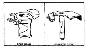
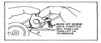
Cast throttles, Fig. 60, Illustration 1, are removed by
backing off the idle speed adjusting screw until the
throttle clears the retaining lug on the carburetor body.
Fig. 61.
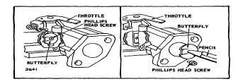
Stamped throttles, Fig. 60, Illustration 2, are removed by
using a Phillips screw driver to remove the throttle valve
screw. After removal of the valve, the throttle may be
lifted out. Reverse procedure to install. Fig. 62.
Illus. 1
Illus. 2
Fig. 60 - Throttle Types
Fig. 61 - Removing Old Style Throttles
Fig. 62 - Removing and Installing
New Style Throttles
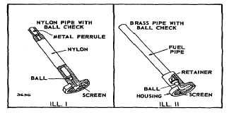
Fuel Pipe
The fuel pipe contains a check ball and a fine mesh
screen. To function properly, the screen must be clean
and the check ball free. Fig. 63. Replace pipe if screen
and ball cannot be satisfactorily cleaned in carburetor
cleaner. DO NOT LEAVE CARBURETOR IN CLEANER
MORE
THAN
1/2
HOUR
WITHOUT
REMOVING
NYLON PARTS. Nylon fuel pipes, Fig. 64, Illustration 1,
are remove and replaced with a 9/16" 6 point socket.
Fig. 63. Brass fuel pipes, Illus. II, are removed by
clamping the pipe in a vise and prying out as shown in
Fig. 65.
Fig. 63 - Fuel Pipes
18