TM 9-2350-238-10
TRACK–CONTINUED
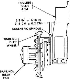
SPINDLE AND IDLER ARM CLEARANCE
Make sure placement of spindle is correct.
Proper placement of spindle in arm is when
approximately 5/8 in. (1.6 cm) of threaded
portion of spindle extends outside of arm, If
placement is incorrect, rotate spindle either in
or out to achieve proper clearance as follows:
1 Decrease track tension.
3-46, steps 1 thru 4.
2 Adjust left side spindle:
Refer to page
a.
Insert 10 in. (25.4 cm) of bar (item
5, appx B) through hub flange into
eccentric shaft spindle.
b. TO increase clearance to 5/8 in, (1.6
cm), drive vehicle forward until spin-
dle has rotated 360 degrees.
Measure clearance. Repeat pro-
cedure, if necessary. To decrease
clearance, drive vehicle rearward.
3 Adjust right side spindle:
a.
Insert 10 in. (25.4 cm) of bar (item
5, appx B) through hub flange into
eccentric shaft spindle.
TRACK REMOVAL AND INSTALLATION
1 Drive vehicle on level ground and posi-
tion track shoe to be removed midway
between bottom of drive sprocket and
first road wheel.
b. To increase clearance to 5/8 in. (1.6
cm), drive vehicle rearward until
spindle has rotated 360 degrees.
Measure clearance. Repeat pro-
cedure, if necessary. To decrease
clearance, drive vehicle forward.
3 Block opposite track to prevent vehicle
movement. Do not lock vehicle brakes.
2 Decrease track tension. Refer to page
3-46.
3-48