TM 9-2350-238-10
TRACK–CONTINUED
TRACK REMOVAL AND INSTALLATION–CONTINUED
4
5
6
7
8
9
10
11
Be sure fixtures are seated pro-
perly, Injury to personnel may
result if they fall off.
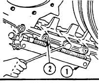
Install two track connecting fixtures (1)
across track shoe to be removed.
Tighten fixtures equally to relieve tension
on track pins.
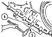
Remove self-locking nut (2) from track
pin.
Do not damage track pin
threads during removal,
Using short leg of drift pin (3) start to
drive track pin (4) out of track shoe (5).
Remove track pin (4) with long leg of
drift pin (3).
Remove track shoe (5) connecting fixture
(l) .
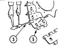
Repeat steps 5 and 6 for remaining track
pin (4) and remove track shoe (5).
Partially install one self-locking nut (2) on
each track pin (4).
Position track shoe (5) being installed at
one end of disconnected track. Lift shoe
approximately 15 degrees to aline hex-
agon shape of bushing and insert track
pin (4). Drive track pin through shoes by
tapping lightly with hammer on end of
nut. Install remaining self-locking nut (2)
on opposite end of track pin (4).
Install two track connecting fixtures (1)
across track shoes to be connected and
tighten equally until holes in ends of
track are aligned, Connect shoes with
track shoe track pin (4) as in step 10
and install remaining self-locking nut (2).
12 Tighten all nuts as much as possible.
Remove track connecting fixture. As
soon as possible, have unit maintenance
personnel torque nuts to 160-200 ft-lb
(216-270 N-m).
NOTE
A minimum of 1/8 track pin
thread must extend through
both track pin nuts.
13 Adjust track tension. Refer to page 3-45.
3-49