TM 9-2350-256-20-1
0085 00
CORRECTIVE ACTION Continued
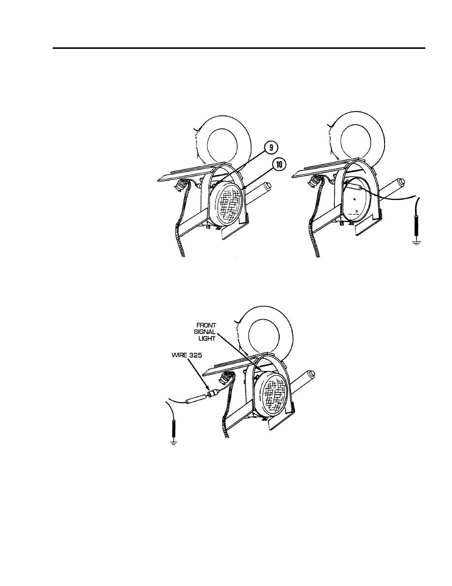
11. Loosen three screws (9) and remove light door with lamp (10). Place red lead of multimeter in
connector and black lead to ground. Turn MASTER and FLASHER switches on and check for voltage.
Turn MASTER and FLASHER switches OFF. If voltage is present, replace lamp (see WP 0177 00). If
voltage is not present, go to step 12.
12. Install light door with lamp (10) and tighten three screws (9). Disconnect wire 325 from front signal
light. Place red lead of multimeter in wire 325 and black lead to ground. Turn MASTER and FLASHER
switches ON and check for voltage. Turn MASTER and FLASHER switches OFF. If voltage is present,
replace front signal light assembly (see WP 0177 00). If voltage is not present, go to step 13.
0085 00-9


