CHAPTER 9: MAINTENANCE OF HULL- AND CAB-RELATED COMPONENTS
TM 9-2350-256-20
9-80 REPLACE/REPAIR/SERVICE SERVICE BRAKE CONTROLS AND LINKAGES-Continued
41
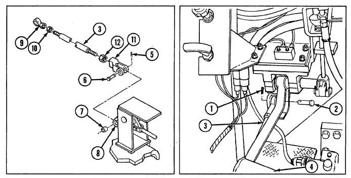
Install rod end (9), nut (10), clevis (11), and nut (12) to rod assembly (3).
42
Connect rod assembly (3) to brake cam assembly (8) with straight pin (6), bearing (7), and new cotter pin (5).
43
Install rod assembly (3) to brake pedal (4) with straight pin (2) and new cotter pin (1).
e. ALINEMENT AND ADJUSTMENT
NOTE
Prior to performing any brake control alinement or adjustment, do the following:
Block vehicle in place and fully release vehicle brakes (refer to TM 9-2350-256-10).
Disconnect left and right brake lever rods from brake-apply levers.
Check each brake-apply lever (point 1). Each lever must be in its fully released position against its external
stop with no free travel. If not, use a 9/16-in. socket wrench and, while pushing in with socket wrench to
release adjustment bolt, turn bolt clockwise to position each lever against its stop.
Alinement
1
Loosen nuts on linkage rods and insert 1/8-in.- (3.2-mm-) diameter locating pins at points indicated. Adjust rods as
necessary to permit pinning.
2
While brake control pedal is pinned, adjust brake control pedal height stop.
3
With brake-apply levers in fully released position against their stops, adjust rear brake rods equally at both ends
until clevis holes in rod ends aline with bottom holes in brake-apply levers. Connect rods to levers.
9-196