SECTION V: CONROLS AND LINKAGES
TM 9-2350-256-20
19
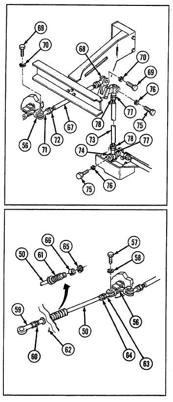
Install rod end (77) and nut (78) to each end of rod
assembly (73).
20
Install rod assembly (73) to levers (68 and 74) with
two screws (75) and two new lockwashers (76).
21
Install rod end (71) and nut (72) to each end of rod
assembly (67).
22
Install rod assembly (67) to levers (56 and 68) with
two screws (69) and two new lockwashers (70).
23
Install rubber boot (61), rubber bushing (66), and
clamp (65) to rod assembly (50). Do not tighten
clamp.
24
Install rod end (63) and nut (64) to one end of rod
assembly (50) and slide other end of rod assembly
through bulkhead (62).
25
Connect rod assembly (50) to lever (56) with screw
(57) and new lockwasher (58).
26
Install rod end (59) and nut (60) .to rod assembly (50).
NOTE
Linkage must be completely installed,
alined, and adjusted before cementing
rubber boot in place.
27
With control adjusted and brake pedal released,
ensure rubber boot (61) is extended to 5-5/8 in. (142.9
mm), tighten clamp (65), and cement rubber boot to
bulkhead (62) with adhesive.
9-193