SECTION V: CONROLS AND LINKAGES
TM 9-2350-256-20
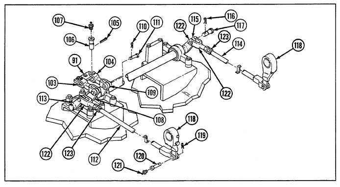
d. INSTALLATION
1
Install long right shaft (133) to two bearing units (134 and 135).
2
Install levers (109 and 115) with retaining ring (132) at each end of long right shaft (133).
3
Install lever (108) with retaining ring (131).
4
Install short left shaft (128) to two bearing units (126 and 127).
5
Install lever (113) with retaining ring (125) and lubrication fitting (124).
6
Install two bearing units (126 and 127) each with two new lockwashers (130) and two screws (129).
7
Install two bearing units (134 and 135) each with two new lockwashers (137) and two screws (136).
8
Install nut (123) and clevis (122) to each end of rod assemblies (112 and 114).
9
Connect rod assembly (112) to lever (113) with straight pin (117) and new cotter pin (116). Install rod assembly to
brake-apply-and-slack adjuster lever (118) with grooved pin (120), lubrication fitting (121), and new cotter pin (119).
10
Connect rod assembly (114) to lever (115) with straight pin (117) and new cotter pin (116). Install rod assembly to
brake-apply-and-slack adjuster lever (118) with grooved pin (120), lubrication fitting (121), and new cotter pin (119).
11
Install yokes (103 and 104) to levers (108 and 109) each with straight pin (111) and new cotter pin (110).
12
Install plate assembly (91) to yokes (103 and 104) with two grooved pins (106), two new cotter pins (105), and two
lubrication fittings (107).
9-191