SECTION V: CONTROLS AND LINKAGES
TM 9-2350-256-20
1
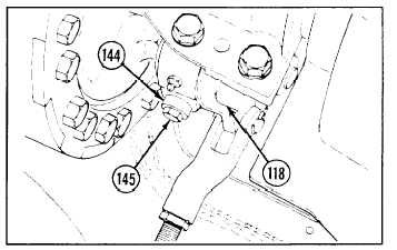
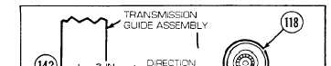
Apply brakes and check amount of brake-apply-and-slack adjuster lever (118) travel. Each lever (right or left)
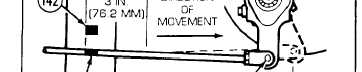
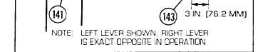
must travel not less than 3 in. (76.2 mm), measured at outer hole (143) in end of lever. With brakes applied,
black mark (141) on brake rod should aline with black mark (142) on brake adjustment gage.
NOTE
Adjustment may be made through access holes in bottom rear of hull.
2
Release brakes and press in locking ring (144). Turn adjustment bolt (145) clockwise to shorten travel or
counterclockwise to lengthen travel, as required. (Shortening brake-apply-and-slack adjuster lever [118]
tightens brakes.)
NOTE
Follow-on maintenance:
Only install or close items necessary to gain access to area of linkage
requiring removal.
•Install oddment tray (see paragraph 9-104)
•Install toolbox rack (see paragraph 9-103)
•Install ammunition rack (see paragraph 9-100)
•Install air inlet grilles as necessary (see paragraph 9-57)
•Install air inlet doors as necessary (see paragraph 9-56)
•Install cab subfloor plates (see paragraphs 9-1 through 9-23)
•Install left-side air cleaner (see paragraph 4-24)
•Install powerplant (see paragraph 3-1)
9-81 REPLACE/REPAIR BRAKE PEDAL AND BRACKET ASSEMBLY
THIS TASK COVERS
a. Removal
b. Disassembly
INITIAL SET-UP
Tools:
•Tool kit, general mechanic’s (Appendix C, item 53)
•Pliers, retaining ring (Appendix C, item 30)
c. Assembly
d. Installation
Parts-Continued:
*Pins, cotter (7) (Appendix G, item 216)
*Pins, cotter (2) (Appendix G, item 227)
Parts:
•Lockrvashers (4) (Appendix G, item 131)
•Lockwashers (6) (Appendix G, item 132)
•Lockwashers (4) (Appendix G, item 153)
Reference:
Appendix J
Equipment Condition:
Neutral safety switch removed (see paragraph 6-14)
Change 1
9 - 1 9 9