SECTION V: TROUBLESHOOTING
TM 9-2350-256-20
WARNING
Remove all jewelry such as rings, dog tags ,
bracelets, etc. If jewelry contacts a metal
surface a direct short may result in instant
heating of tools, damage to equipment, and
injury or death to personnel.
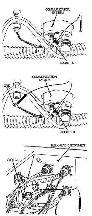
A Disconnect switch panel, radio, and bilge pump to
bulkhead wiring harness from both communications
systems. Place red lead of multimeter in one socket
A of wire 48 and black lead to ground. Turn
MASTER switch on and check for voltage. Then
place red lead of multimeter in other socket A of
wire 48 and black lead to ground and check for
voltage. Turn MASTER switch OFF. If voltage is
present in both sockets, go to step B. If voltage is
present in one or not present in either, go to step C.
B Disconnect one ground wire from bulkhead. Place
red lead of multimeter in socket B of ground wire
and black lead on other end of ground wire. Check
for continuity. Disconnect other ground wire from
bulkhead. Place red lead of multimeter in socket B
of ground wire and black lead on other end of ground
wire. If continuity is present, troubleshoot master
relay (see paragraph 2-19, master relay fails to
operate). If continuity is not present,
repair/replace ground wire of switch panel, radio,
and bilge pump to bulkhead wiring harness (see
paragraph 6-53).
C Reconnect ground wires to hull and switch panel,
radio, and bilge pump to bulkhead wiring harness
to both communications systems. Disconnect wire 48
pin A from bulkhead to master relay wiring
harness. Place red multimeter lead in socket and
black lead to ground. Turn MASTER switch on and
check for voltage. Turn MASTER switch OFF. If
voltage is present, repair or replace switch panel,
radio, and bilge pump to bulkhead wiring harness
(see paragraph 6-53). If voltage is not present,
troubleshoot master relay circuit (see paragraph
2-19, master relay fails to operate).
2-239