SECTION V: TROUBLESHOOTING
TM 9-2350-256-20
WARNING
Remove all jewelry such as rings, dog tags,
bracelets, etc. If jewelry contacts a metal
surface a direct short may result in instant
heating of tools, damage to equipment, and
injury or death to personnel.
E
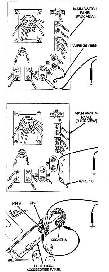
Reconnect switch panel to gage panel and
miscellaneous switches wiring harness to main switch
panel. Remove main switch panel (see paragraph 6-
10). Place jumper wire from bracket to hull to ground
the panel. Disconnect wire 38/999 from 15 A circuit
breaker. Place red lead of multimeter on terminal of
15 A circuit breaker and black lead to ground. Turn
MASTER switch on and check for voltage. Turn
MASTER switch OFF. If voltage is present,
repair/replace wire 38/999 of main lighting and B.O.
selector switch wiring harness (see paragraph 6-69).
If voltage is not present, go to step F.
F
Reconnect wire 38/999 to 15 A circuit breaker.
Disconnect wire 10 from 15 A circuit breaker. Place
red lead of multimeter in wire 10 and black lead to
ground. Turn MASTER switch on and check for
voltage. Turn MASTER switch OFF. If voltage is
present, replace 15 A circuit breaker (see paragraph
6-10). If voltage is not present, repair/replace wire 10
of main lighting and B.O. selector switch wiring
harness (see paragraph 6-69).
G
Disconnect electrical accessories panel wiring harness
from electrical accessories panel. Place a jumper
wire from pin A to socket A of wire 38/59. Place red
lead of multimeter on pin F of wire 38 and black lead
to ground. Turn MASTER switch on and check for
voltage. Turn MASTER switch OFF. If voltage is
present,
repair/replace
wire
38
of
electrical
accessories panel wiring harness (see paragraph 6-
47). If voltage is not present, go to step H.
2-243