SECTION V: TROUBLESHOOTING
TM 9-2350-256-20
WARNING
Remove all jewelry such as rings, dog tags,
bracelets, etc. If jewelry contacts a metal
surface a direct short may result in instant
heating of tools, damage to equipment, and
injury or death to personnel.
D
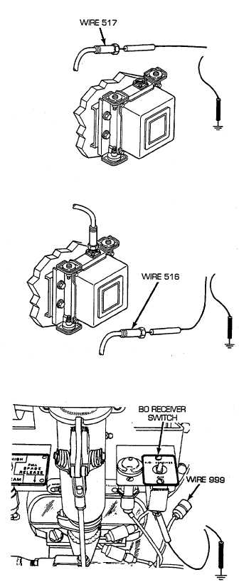
Disconnect infrared power supply to driver's periscope
lead assembly from infrared power supply. Place red
lead of multimeter in socket of wire 517 and black
lead to ground. Turn MASTER and B.O. RECEIVER
switches on and check for voltage. Turn MASTER
and B.O. RECEIVER switches OFF. If voltage is
present, replace/repair infrared power supply to
driver's periscope lead assembly (see paragraph 6-
100). If voltage is not present, go to step E.
E
Disconnect switch panel to gage panel and
miscellaneous switches wiring harness from infrared
power supply. Place red lead of multimeter in wire
516 and black lead to ground. Turn MASTER and
B.O. RECEIVER switches on and check for voltage.
Turn MASTER and B.O. RECEIVER switches OFF. If
voltage is present, replace/repair infrared power
supply (see paragraph 9-39). If voltage is not present,
go to step F.
F
Disconnect wire 999 from infrared power supply side
of B.O. RECEIVER switch. Place red lead of
multimeter on switch terminal and black lead to
ground. Turn MASTER and B.O. RECEIVER
switches on and check for voltage. Turn MASTER
and B.O. RECEIVER switches OFF. If voltage is
present, repair/replace infrared power supply to B.O.
RECEIVER switch wire 999 of switch panel to gage
panel and miscellaneous switches wiring harness (see
paragraph 6-56). If voltage is not present, go to step
G.
2-251