CHAPTER 2: VEHICLE MAINTENANCE INSTRUCTIONS
TM 9-2350-256-20
2-19 ELECTRICAL TROUBLESHOOTING-Continued
B.O. SERVICE CONDITION (IR HEADLIGHTS)-Continued
WARNING
Remove all jewelry such as rings, dog
tags, bracelets, etc. If jewelry contacts a
metal surface a direct short may result in
instant heating of tools, damage to
equipment, and injury or death to
personnel.
O
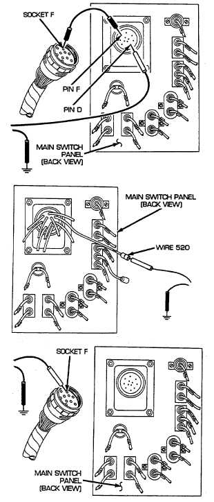
Reconnect wire 520 to B.O. SELECTOR switch.
Disconnect main lighting and master relay wiring
harness from main lighting switch. Place a jumper
wire from pin F to socket F. Place red lead of
multimeter on pin D of wire 520 and black lead to
ground. Turn MASTER switch on, UNLOCK and
move main lighting to B.O. DRIVE position, and
check for voltage. Turn MASTER and main lighting
switches OFF. If voltage is present, go to step P. If
voltage is not present, go to step Q.
P
Reconnect main lighting and master relay wiring
harness to main lighting switch. Disconnect wire 520
at female connector, near main lighting switch.
Place red lead of multimeter in female connector of
wire 520 and black lead to ground. Turn MASTER
switch on, UNLOCK and move main lighting switch
to B.O. DRIVE position, and check for voltage. Turn
MASTER and main lighting switches OFF. If voltage
is present, repair/replace wire 520 of B.O. selector
lead assembly (see paragraph 6-68). If voltage is
not present, repair/replace wire 520 of main lighting
and master relay wiring harness (see paragraph 6-
70).
Q
Place red lead of multimeter in socket F of wire 15
and black lead to ground. Turn MASTER switch on
and check for voltage. Turn MASTER switch OFF.
If voltage is present, replace main lighting switch
(see paragraph 6-10). If voltage is not present, go to
step R.
2—
296