TM 9--2350--292--20--1
0193 00--4
ENGINE REAR MOUNT AND BASE ASSEMBLY REPAIR -- CONTINUED
0193 00
Disassembly
NOTE
Front and rear barrel nuts are threaded in opposite direc-
tions. Keep nuts separated to ensure proper placement
during reassembly.
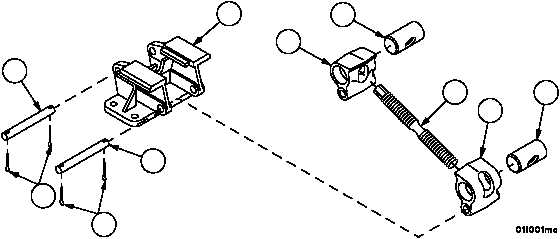
1. Remove four cotter pins (47) and two headless pins (48) from base (49). Discard cotter pins.
2. Remove tension bolt (7), two jaws (50), front barrel nut (51) and rear barrel nut (52) as an assembly from base
(49).
3. Remove two jaws (50), front barrel nut (51) and rear barrel nut (52) from tension bolt (7).
4. Inspect parts for damage and replace as required.
Assembly
NOTE
Front and rear barrel nuts are threaded in opposite direc-
tions. Ensure proper placement during assembly.
1. Install rear barrel nut (52), front barrel nut (51) and two jaws (50) on tension bolt (7).
CAUTION
Make sure jaws are spaced evenly on tension bolt. Equip-
ment damage may occur if jaws are not adjusted properly
prior to installation.
2. Install tension bolt (7), two jaws (50), front barrel nut (51) and rear barrel nut (52) as an assembly in base (49).
3. Install two headless pins (48) in base (49) and through two jaws (50). Install four new cotter pins (47) in two
headless pins (48).
Figure 3
49
48
47
47
48
50
51
7
50
52


